Understanding AC Transformer Construction: Core-type and Shell-Type AC Transformers
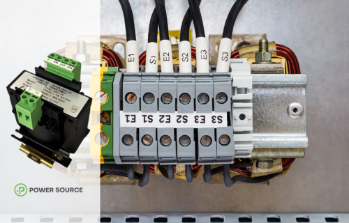
The core of an AC transformer guides magnetic flux between primary and secondary windings. There are two main ways to arrange these windings: core-type and shell-type.
Core-Type Transformers
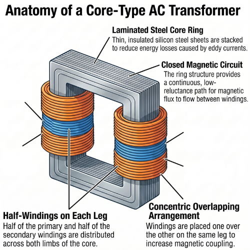
Core-type transformers feature windings placed around the outer limbs of the core. Each winding is usually split equally between the two limbs. This ensures both windings share the same magnetic path and supports efficient energy transfer. In core-type transformers, most magnetic flux links the primary and secondary windings. Some flux escapes as leakage flux through steel and air. Core-type transformers often have higher leakage inductance than shell-type designs. These transformers are simple to construct and suitable for medium- and high-power applications.
Shell-Type Transformers
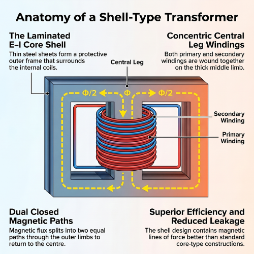
In a shell-type transformer, the magnetic core surrounds the windings, with both primary and secondary windings wound onto a single central limb, whilst two outer limbs complete the magnetic circuit. The central limb will carry the full magnetic flux, as it features twice the cross-sectional area of each out limb, while the latter carries half the total flux.
The windings are often found stacked as pancake or sandwich coils with insulated flat conductors to control leakage and maintain clearances. The compact arrangement creates two parallel flux paths in the outer limbs, reducing leakage flux, shortening the magnetic path and providing strong support during short circuits. Shell-type transformers are usually more efficient and have reduced flux leakage.
Shell-type transformers are common in control, electronic and instrument transformers where compact size and short-circuit strength are important.
Shared Design Elements Amongst Core-Type and Shell-Type Transformers
Both transformer types may have different layouts, but they still share similar features, relying on permeable steel cores constructed from thin silicon steel laminations to minimise hysteresis and eddy-current losses.
Typical shapes of these laminations can be “E”, “I”, “U”, and “L”- shaped, and they can be stacked in alternating fashion, reducing air gaps and reluctance in the magnetic circuit. Both design types will have given ratings and frequencies, with the goal of operating at similar flux densities and temperature rises, so that installers can choose the difference based on factors such as mechanical strength, installation, cooling, insulation, and cost.
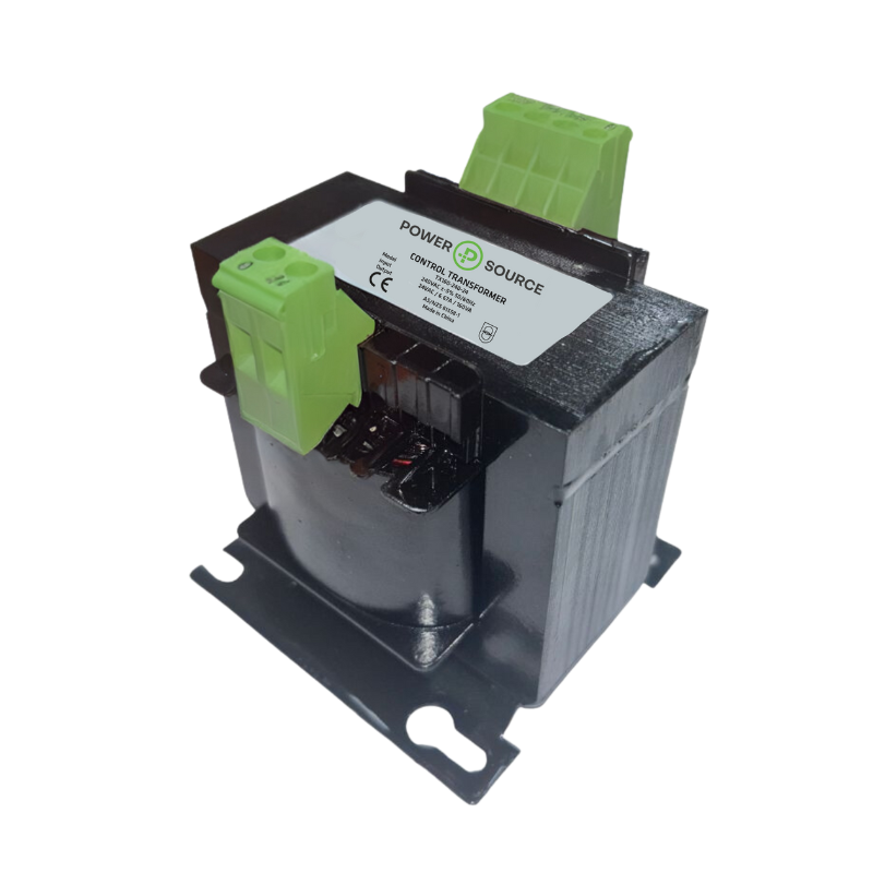
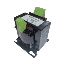
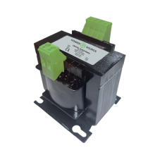
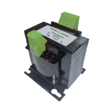
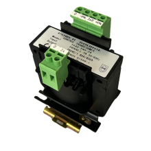
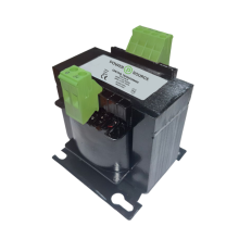
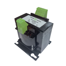
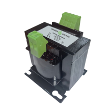
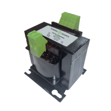
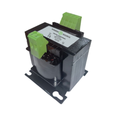
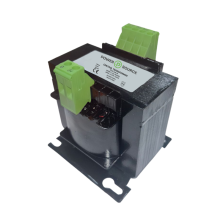
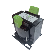
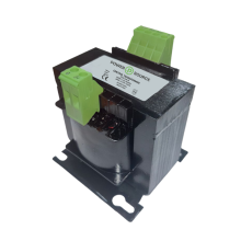
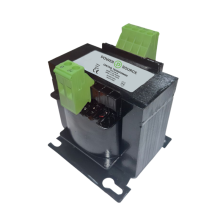
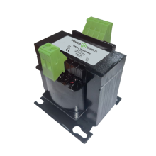
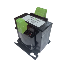
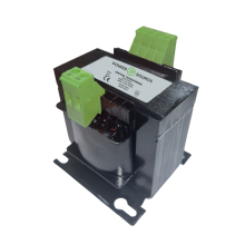
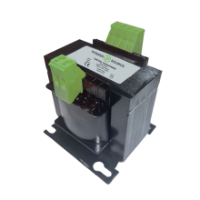
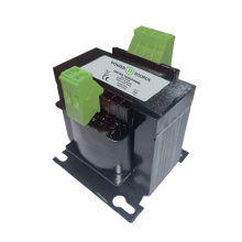
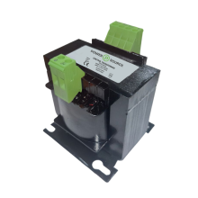
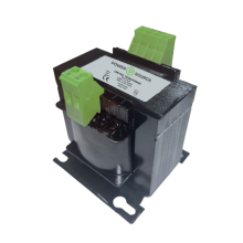
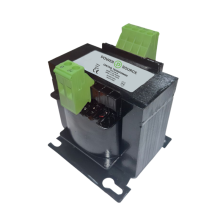
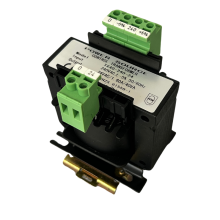
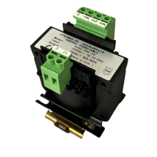
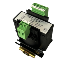
Power Source TX Series are shell-type AC transformers
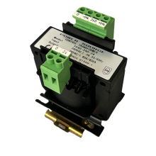
Our Power Source TX series is a range of shell-type AC transformers designed for control transformer applications. These transformers are magnetic transformers, providing galvanic isolation between the primary and secondary windings. Although this range is primarily for control AC transformers, some models within it offer 1:1 power input-to-output ratios and provide isolation if needed.
Learn more about Power Source here.
The TX range can handle power ratings from 40VA to 2500VA, with both 240VAC and 415VAC inputs, and outputs ranging from 12VAC to 240VAC. This range is also designed with 5% +/- terminals to cater to more specific installation needs. For users requiring lower-voltage AC power, the TX series offers DIN-rail mounting for the TX40, TX63, and TX100 models.
If you’d like to learn more about the Power Source TX series, speak with the ADM team today! Send any questions to the team via our contact page here or call them directly on 1300 236 467.